
Abstract
Spent lithium ion batteries (LIBs) are piling up from the electric-vehicle revolution and the increased demand in portable electronics. Currently, there is no environmentally friendly LIB recycle process really commercialized. This paper describes a series of experiments to advance the knowledge about recovery of metals from the spent battery cathode materials and to develop a novel environmentally friendlier closed-loop hydrometallurgical process. The leaching conditions are optimized by the bench scale experiments and various options for recovering critical LIB cathode metals are investigated. The semi-continuous locked-cycle campaigns document the dynamics of the recycled streams and yield much useful data. The behaviour of the leached cobalt is strongly affected by sulphate supersaturation and the location of sodium sulphate crystallization, but successful operation can be maintained when the sodium sulphate level is carefully controlled. These solution properties are the key factors when recycling spent cathode metals using systems based on sulphuric acid and sodium salts. Experimental results also show that the systems may reach supersaturation when circulating loads are incorporated, demonstrating the significance of sulphate levels in such systems. The closed-loop flowsheets are developed to recover metals, reduce discharges, and minimize environmental impact in the recycling of the spent cathode materials.
Export citation and abstract BibTeX RIS
The commercialization of lithium-ion batteries (LIBs) has resulted in the vigorous development of various proprietary designs and formulations for their cathode materials. A LIB cathode is made up of an active material such as lithium-cobalt oxide (LiCoO2 also referred to as LCO), commonly used in laptop batteries, cell phones, and electric vehicles; lithium iron phosphate (LiFePO4 also referred to as LFP), used in energy storage and electric vehicles; lithium nickel manganese cobalt oxide (LiNi1/3Co1/3Mn1/3O2 also referred to as NMC), used in electric vehicles; lithium nickel cobalt aluminium oxide (LiNi0.8Co0.15Al0.05O2 also referred to as NCA); used in electric vehicles; or lithium-manganese dioxide (LiMnO2 or LMO), used in electric power tools and plug in hybrid electric vehicles. In general, LIBs have relatively high energy/power densities and long cycle-life, are suitable for portable electronics, electric vehicles and stationary power stations. However, their charge capacity will slowly degrade with regular use and will eventually need to be replaced. The limited nature abundances of the electrode materials such as lithium, cobalt and nickel can limit their sustainable usage particularly in large-scale applications where the large quantity of the electrode materials is necessary. To mitigate this limitation, recycling the end-of-life electrode materials for recovering the valuable raw materials are definitely needed.
Regarding the recycling of the spent cathode materials such as Co-containing ones, the incorporated other metal components can add some complexity to the recycling of the spent batteries. The range of materials used would require a multi-stage treatment approach to separate metals when hydrometallurgical methods are applied to the mixed cathode materials. Normally, the hydrometallurgy can break down the battery components by leaching and produces generic products which can then be tailored to any new cathode composition. The most common reagent reported for leaching cathode material is sulphuric acid. In addition to acid, the leach generally requires a reducing agent to control the oxidation state of the cathode metals. The cobalt, nickel and manganese in cathode materials are typically present at higher oxidation states. 1 To accelerate the rate of dissolution of these metals from battery material, various reducing agents have been applied. Among all reducing agents used in leaching lithium ion battery cathode materials with acid, H2O2 presents the best option. 2–5 However, it is also known that peroxide easily decomposes, leading to high reagent consumption that can render commercial processes uneconomic. Recently, ferrous and ferrous-cuprous catalysed leaching systems, 6,7 and sodium metabisulphite 8 were reported as the effective alternatives to the conventional peroxide method. Leaching with sodium metabisulphite could not only dissolve the cathode metals in acid but also minimized the dissolution of impurities like aluminium (Al) and copper (Cu) in leach solution. 8 Impurities like Al and Cu needs to be monitored because their dissolution could increase reagent requirements and add complexity to the subsequent metal separation and purification stages.
To recover dissolved metals from acid leach solutions, solvent extraction methods have been applied and demonstrated by several researchers. 9,10 However, great care needs to be taken to avoid cross-contamination when using multiple reagents, and the cost and complexity of solvent extraction processes are hard to justify for relatively small-scale LIB cathode re-processing operations. 1 Compared to solvent extraction, precipitation methods are simpler and can be efficient if the conditions are selected carefully. Precipitation methods recover metals as mixed metal products with different compositions (hydroxides, carbonates, sulphides). With this method, a complete separation of Ni and Co is difficult as these metals (of the same oxidation state) are situated next to each other in the stability diagram. 11 Separation of the mixed metal products can be made possible through the re-solubilisation of mixed Co-Ni hydroxides under oxidative conditions in a pH range of 2.3 to 5.5, resulting in an almost complete nickel dissolution while leaving cobalt in the precipitate. 12
In the current research, three different cathode compositions, NMC, NCA, and LMO, have been leached in acid with the addition of sulphur dioxide, followed by a series of precipitation stages to recover the solubilised metals either simultaneously or sequentially. A number of process options are considered and optimized in bench-type experiments and the resulting flowsheet is demonstrated in the locked-cycle semi-continuous campaigns using LCO cathode material.
Experimental
Materials and methods
The standard cathode materials (> 99.99% pure) for validation the methods were obtained as battery-grade reagents from MTI Corp. All chemicals (H2SO4, NaOH, Na2CO3, NaHS, Na2S, LiOH, (NH4)2CO3) were analytical grade, and all solutions were prepared with deionized water.
Leaching tests were conducted in a 1000 ml baffled reactor equipped with a condenser and overhead agitator. The reactor was placed in a heating mantle for temperature control. The cathode material was mixed with sulfuric acid solution and SO2 was sparged into the resulting slurry, targeting a pre-determined ORP (Oxidation-Reduction-Potential) set point. Parameters including acid concentration, leaching time, pH and ORP were monitored and controlled as necessary. At the end of the leach stage, the products (leachate and reaction residue) were filtered and the leach residue was thoroughly washed with DI water. Subsequent precipitation tests were done using the same type of reactor. At the beginning of a precipitation test, the solution was sparged with nitrogen gas to remove the dissolved oxygen. Typically, 200 ml of the leachate was used for batch tests studying different reagents and conditions. At the end of each test, the products were filtered, and the precipitate was washed thoroughly and dried at 70 °C. A sketch of the reactor is given in Fig. 1.

Figure 1. Reactor setup used for leach and precipitation testing.
Download figure:
Standard image High-resolution imageThe quantitative metal contents for Al, Mn, Ni, Co and Li were analyzed by ICP-OES. The concentration of sulphate was determined using the method, sulphate by turbidimetric (EPA 9038), where sulphate ion was converted to a barium sulphate suspension under controlled conditions. The resulting turbidity was measured using a HACH TU5200 laser turbidimeter. The concentration of dithionate was directly measured by HPLC using sodium perchlorate eluent along with an AS17 ion exchange column.
The locked-cycle campaign used 100 grams of cathode material per cycle at a pulp density of 8%, with 1.2M H2SO4 to maintain a pH close to 1.5 and an ORP target of 350 mV. The leach residence time was 2 h per cycle. The temperature was maintained at 50 °C after the initial exothermic phase to help ensure that the leach reaction went to completion.
The first campaign used sodium hydroxide addition under nitrogen sparging to precipitate cobalt as cobalt hydroxide. The residence time was 2 h. The filtrate from the cobalt hydroxide precipitation stage was heated to 95 °C and mixed with 1.2 times the stoichiometric requirement of sodium carbonate for 0.5 h to precipitate lithium carbonate. The precipitated lithium carbonate was filtered and washed with the saturated Li2CO3 at 95 °C. Except for Cycle 1, all the saturated Li2CO3 wash solution was prepared using Li2CO3 solids generated from previous cycles. The filtrate from the lithium precipitation stage was cooled to 5 °C to initiate Na2SO4 crystal formation. The crystallization stage was run for 2 h before the resulting crystals were filtered. The crystallization filtrate and leach residue wash solution were then combined with evaporated wash solution from the cobalt precipitation stage and the resulting solution was acidified for use as the leach solution for the next cycle.
In the second locked-cycle campaign, the Co and Li were precipitated together by adding a 1.2 times stoichiometric quantity of sodium carbonate at 95 °C to the leach solution after first adjusting the pH to 11 with sodium hydroxide to form cobalt hydroxide. The combined precipitate was filtered and washed with a saturated Li2CO3 solution (using reagent Li2CO3). As with the first campaign the filtrate was then chilled to 5 °C for 2 h before filtering the resulting sodium sulphate crystals. For this campaign, the filtered crystals were also subjected to a re-pulp wash in the saturated Na2SO4 solution, also at 5 °C. The crystallization filtrate was then combined with the crystal wash solution, Co-Li precipitate wash solution and the leach residue wash solution. This combined solution was evaporated to the target leach volume and acidified for use as the leach solution for the next cycle.
Results and Discussion
Evaluating leaching conditions for various cathode materials
Three different cathode materials, NMC, NCA and LMO, were leached using sulphuric acid with the objective of extracting valuable metals. Typical leach conditions were 10% solids, 1.2 M H2SO4 and SO2 sparging targeting an ORP of 350 mV. To determine the optimal reaction time, kinetic samples were taken at time intervals. Figures 2a–2c presents examples of the leaching kinetics of NMC, NCA, and LMO material.

Figure 2. Leaching kinetics (a) NMC, (b) NCA, (c) LMO.
Download figure:
Standard image High-resolution imageFigure 2a shows that 80% of metals (Li, Co, Ni, Mn) from NMC are extracted within 30 min, and that almost a complete dissolution of cathode material can be seen within 2 h of the reaction time. A repetitive test shows 97.8% reproductivity. Further leaching tests with NMC indicated that the acid concentration could be reduced to 1.0M H2SO4 without sacrificing metal extraction. The same was true for leaching tests with NCA shown in Fig. 2b and LMO shown in Fig. 2c. The total metal extractions were over 99% in all tests with NMC and NCA materials. The extractions were similar for LMO material, and it was found that less acid (∼0.8M) was required to achieve the same overall metal extraction. The selected test results are given in Table I.
Table I. Leach tests results with NMC, NCA and LMO cathode materials.
| Operation Conditions | Extraction | Concentration | ||||||||||
|---|---|---|---|---|---|---|---|---|---|---|---|---|
| Solids | H2SO4 | SO2 | pH | ORP | Li | Co | Ni | Mn | Total | S2O6 2− | SO4 2− | |
| Test ID | % | M | g | mV | % | % | % | % | G | g l−1 | g l−1 | |
| NMC-2-LT7 | 10 | 1.0 | 119 | 1.0 | 486 | 99.8 | 100 | 99.9 | 100 | 87.8 | 23.9 | 184 |
| NMC-2-LT8 | 8 | 1.0 | 59.6 | 1.0 | 487 | 99.7 | 99.9 | 99.9 | 99.9 | 34.4 | 25.1 | 150 |
| NCA-LT4 | 10 | 1.0 | 59.6 | 1.5 | 412 | 100 | 100 | 100 | 100 | 33.1 | 29.9 | 166 |
| NCA-LT5 | 10 | 1.2 | 57.3 | 1.0 | 562 | 99.4 | 99.8 | 99.8 | 99.8 | 32.3 | 25.2 | 198 |
| LMO-LT7 | 10 | 0.8 | 69.1 | 0.6 | 637 | 97.9 | — | — | 98.3 | 23.3 | 21.2 | 188 |
| LMO-LT8 | 10 | 0.6 | 69.8 | 1.2 | 630 | 99.1 | — | — | 99.8 | 16.9 | 22.5 | 177 |
Along with metal extraction values, Table I presents the sulphate and dithionate concentrations in leach solutions. The dithionate concentration varies between 21–30 g l−1 and sulphate concentrations ranges from 150 to 198 g l−1. These values are important to monitor to avoid exceeding the saturation levels and generating undesirable precipitates, particularly in the closed systems with the circulating solution streams. Examination of the complete test results revealed that higher acid concentrations and less SO2 addition generated less dithionate. Although, the SO2 addition was not crucial for lithium dissolution, this reagent was necessary to dissolve other metals. The SO2 addition impacts the oxidation state of the transition metals, maintaining them in their more soluble forms.
Evaluating options for recovering solubilized metals
Three different precipitating agents were used to recover the dissolved metals from leach solutions. Sodium hydroxide was used to recover metals as hydroxides. Sodium carbonate produced carbonate compounds and was mainly used for Lithium recovery. Sodium sulphide formed insoluble metal sulphides and was tested as an option to minimize the Mn in Ni/Co mixed metal precipitates. Some tests explored the option of recovering all metals simultaneously and some used a sequential precipitation approach and various conditions were tested for each approach. Metal recovery results from NMC leach solutions are given in Table II.
Table II. Precipitation test results using NMC leachate.
| Conditions | Distribution | |||||||||
|---|---|---|---|---|---|---|---|---|---|---|
| NaOH | Na2S | Na2CO3 | pH | Temp | Dry Wt. | Li | Co | Ni | Mn | |
| Test | g/Kg a) | g/Kg a) | g/Kg a) | OC | g | % | % | % | % | |
| NMC-2-PT2 | ||||||||||
| Stage 1 (Ni, Co) | 538 | — | — | 8.0 | 20 | 19.0 | 2.9 | 95.5 | 97.8 | 21.9 |
| Stage 2 (Mn) | — | — | 359 | 10.0 | 20 | 4.7 | 1.4 | 2.8 | 1.4 | 49.5 |
| Stage 3 (Li) | — | — | 523 | 10.6 | 95 | 27.7 | 27.7 | 0.01 | 0.01 | 0.05 |
| NMC-2-PT3 | ||||||||||
| Stage 1 (Ni, Co) | 550 | — | — | 7.8 | 50 | 20.9 | 3.4 | 98.8 | 99.5 | 36.9 |
| Stage 2 (Mn) | — | — | 933 | 10.0 | 20 | 3.2 | 1.6 | 0.64 | 0.27 | 32.9 |
| Stage 3 (LI) | — | — | 523 | 10.6 | 95 | 0.2 | 1.8 | 0.01 | 0.01 | 0.08 |
| NMC-2-PT5 | ||||||||||
| Stage 1 (Ni, Co) | 176 | 339 | — | 5.0 | 20 | 25.0 | 3.1 | 99.6 | 99.9 | 6.6 |
| Stage 2 (Mn) | — | — | 348 | 10.0 | 20 | 5.9 | 2.0 | 0.11 | 0.03 | 68.6 |
| Stage 3 (Li) | — | — | 523 | 10.5 | 95 | 2.1 | 25.2 | 0.002 | 0.001 | 0.04 |
| NMC-2-PT7 | ||||||||||
| Stage 1 (Ni, Co, Mn) | 655 | — | — | 10.0 | 20 | 28.7 | 12.6 | 100.0 | 100.0 | 100.0 |
| Stage 2 (Li) | — | — | 563 | 11.0 | 95 | 2.8 | 29.2 | 0.002 | 0.001 | 0.004 |
The results shown in Table II indicate that increasing the temperature (50 °C in NMC-2-PT3 vs ∼20 °C in NMC-2-PT2) at pH ∼8 can only increase Co and Ni recoveries slightly whereas Mn recovery to the Ni-Co product is increased by 15%. Complete removal of all three metals (Co, Ni and Mn) was achieved when the pH was adjusted to 10 in test NMC-2-PT7. In this test the consumption of caustic increased but the overall reagent requirement was reduced. A small amount of caustic was still needed in test NMC-2-PT5, using sodium sulphide precipitation at pH 5. Co and Ni recoveries for this test were over 99.5%. A small amount of Mn was co-precipitated with the Co and Ni sulphides, but overall, this test showed the most effective separation of Mn from the Co-Ni product. The remaining Mn and Li could then be precipitated as two separate products using the controlled sodium carbonate addition and temperature.
The NCA leach solution required an initial treatment stage to remove Al separately from other metals. The Al was removed through neutralization with caustic at pH 4.5 to 5.5. Within this range, higher pH gave better Al removal. After Al removal, the pH was further increased to above 10 with caustic to collect the Co and Ni as the mixed metal hydroxides. Following that, sodium carbonate was added to recover the lithium. The test results are given in Table III.
Table III. Precipitation test results using NCA leachate.
| Conditions | Distribution | |||||||||
|---|---|---|---|---|---|---|---|---|---|---|
| NaOH | NaHS | Na2CO3 | pH | Temp | Dry Wt. | Li | Co | Ni | Al | |
| Test | g/Kg a) | g/Kg a) | g/Kg a) | °C | g | % | % | % | % | |
| NCA-PT2 | ||||||||||
| Stage 1 (Al) | 117 | — | — | 4.5 | 20 | 0.58 | 0.09 | 0.38 | 0.48 | 56.1 |
| Stage 2 (Co, Ni) | 643 | — | — | 11.5 | 20 | 22.3 | 3.97 | 90.4 | 90.0 | 42.5 |
| Stage 3 (Li) | — | — | 527 | 11.5 | 95 | 2.33 | 26.8 | 0.00 | 0.00 | 0.07 |
| NCA-PT4 | ||||||||||
| Stage 1 (Al) | 131 | — | — | 5.5 | 20 | 1.33 | 0.03 | 1.13 | 1.40 | 98.7 |
| Stage 2 (Co, Ni) | 484 | — | — | 10.5 | 20 | 22.7 | 1.9 | 90.8 | 90.9 | 0.3 |
| Stage 3 (LI) | — | — | 527 | 10.7 | 95 | 2.88 | 31.5 | 0.02 | 0.02 | 0.08 |
| NCA-PT6 | ||||||||||
| Stage 1 (Al, Co, Ni) | 505 | — | — | 10.5 | 20 | 19.4 | 0.99 | 100.0 | 100.0 | 99.2 |
| Stage 2 (Li) | — | — | 527 | 10.6 | 95 | 2.09 | 31.2 | 0.03 | 0.03 | 0.11 |
| NCA-PT8 | ||||||||||
| Stage 1 (Al) | 130 | — | — | 5.03 | 20 | 1.13 | 0.1 | 0.70 | 0.84 | 96.3 |
| Stage 2 (Co, Ni) | 101 | 528 | — | 6.12 | 20 | 35.2 | 4.2 | 92.0 | 91.8 | 2.7 |
| Stage 2 (Li) | — | — | 527 | 10.8 | 95 | 2.85 | 32.5 | 0.00 | 0.00 | 0.03 |
Table III shows that close to 99% of Al can be precipitated from solution at pH 5.5 (NCA-PT4), while just over half of Al (56%) is removed at pH 4.5. Just over 90% of Co and Ni are recovered at both pH 10.5 and 11.5, with the balance lost to entrainment in the voluminous AlOOH precipitate. In test NCA-PT 6, a simultaneous co-precipitation of Al, Co and Ni as hydroxides can be successfully demonstrated at pH 10.5. Sulphide addition in test NCA-PT 8 shows similar levels of Co and Ni recovery to test NCA-PT 4, but the precipitate is significantly larger.
A similar approach was taken in treating LMO leach solution, although the composition was much simpler. Both caustic and carbonate precipitation methods were used to recover Li and Mn from solution. Test results are shown in Table IV.
Table IV. Precipitation test results with LMO leachate.
| Conditions | Distribution | |||||||
|---|---|---|---|---|---|---|---|---|
| NaOH | Na2CO3 | CO2 Sparging Time | pH | Temp | Dry Wt. | Li | Mn | |
| Test | g/Kg a) | g/Kg a) | min | °C | g | % | % | |
| LMO-PT2 | ||||||||
| Stage 1 (Mn) | 740 | — | — | 10.0 | 20 | 19.9 | 0.83 | 100.0 |
| Stage 2 (Li) | — | 297 | — | 10.6 | 95 | 0.91 | 18.3 | 0.01 |
| LMO-PT4 | ||||||||
| Stage 1 (Mn) | 760 | — | — | 10.1 | 50 | 18.9 | 0.69 | 100.0 |
| Stage 2 (Li) | — | 297 | — | 11.3 | 95 | 0.91 | 18.0 | 0.00 |
| LMO-PT6 | ||||||||
| Stage 1 (Mn) | — | 1246 | — | 10.0 | 20 | 31.0 | 23.3 | 100.0 |
| Stage 2 (Li) | — | 297 | — | 11.0 | 95 | 0.00 | 0.00 | 0.00 |
| LMO-PT9 | ||||||||
| Stage 1 (Mn) | 805 | — | 34 | 11.7–8.59 | 20 | 29.5 | 16.8 | 100.0 |
| Stage 2 (Li) | — | 297 | — | 11.6 | 95 | 0.24 | 4.87 | 0.04 |
From Table IV, it is clear that Mn recovery is completed at pH 10 using either caustic or carbonate. The lower concentrations can make the recovery of lithium particularly challenging with LMO, and only about 20% of the initial Li feed is recovered as carbonate, whether the reagent was added as sodium carbonate powder or as CO2 gas sparges in alkaline solution.
Figure 3 summarises the metal recovery from the leach solutions produced from all three cathode material types (NMC, NCA and LMO) as a function of pH. Good recovery values for Co, Ni and Mn can be achieved at pH 10 using the hydroxide system. Similar recovery of Co and Ni can be seen at a lower pH (5.0) with aqueous sulphide addition (not included in Fig. 3). The lithium recovery is low, but the expectation is that the recovery would be increased by recycling lithium-rich process solutions back to the leaching stage, therefore no alternative lithium recovery methods were included in this part of the investigation.

Figure 3. Precipitation efficiency vs pH.
Download figure:
Standard image High-resolution imageLocked cycle testing of LCO cathode material
Following the positive results from bench scale tests, a locked-cycle campaign was initiated to evaluate the effects of the recycled process solutions on overall efficiency. Two different campaigns were run, with each campaign consisting of 10 cycles. Both campaigns were based on the same conditions for leaching an LCO active cathode material, using sulphuric acid and sulphur dioxide under the same target conditions. The main difference between these campaigns was in the subsequent metal recovery flowsheet. The first locked cycle campaign recovered the leached metals sequentially using sodium hydroxide to remove Co followed by sodium carbonate for Li recovery. The second locked cycle campaign used a combination of sodium hydroxide and sodium carbonate to recover both valuable metals simultaneously. After metal recovery, the remaining metal-deficient solutions were treated by chilling for sodium sulphate removal before being recycled back to the next cycle's leaching stage. The chiller was added to lower the equilibrium sulphate concentration and prevent uncontrolled precipitation of sodium sulphate in the system. 13 Evaporation of the recycled solutions was incorporated as needed to maintain the overall water balance.
Figure 4 shows the schematic of the first locked-cycle campaign. The optional of nanofilter showed in Fig. 4 was not executed during the locked-cycle campaign. The extraction values for the first locked-cycle campaign are shown in Fig. 5. Near 100% extractions can be achieved for both metals for the initial 8 cycles.

Figure 4. First lock cycle flowsheet with sequential recovery.
Download figure:
Standard image High-resolution image
Figure 5. LCO leaching results—first locked-cycle campaign.
Download figure:
Standard image High-resolution imageThe recovery values are declined in Cycles 9 and 10 to some extent (82%–88% for both Li and Co). This can be attributed to the changing composition of the recycle streams and will be discussed further. The recoveries of leached metals from solution are shown in Fig. 6. Cobalt is precipitated with sodium hydroxide and lithium is recovered with sodium carbonate. Results indicate consistent cobalt recovery through all cycles of 90% or greater, and a steady rise in lithium recovery with each cycle, as is predicted.
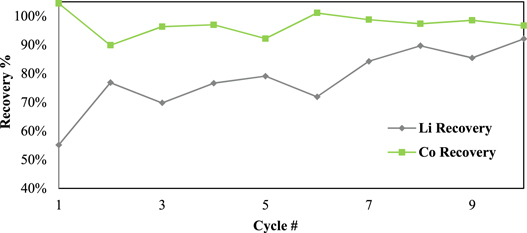
Figure 6. Metal recoveries in the first locked-cycle campaign.
Download figure:
Standard image High-resolution imageTo crystalize the Na2SO4 and remove it from the recycle stream, the filtrate from lithium precipitation was cooled to 5 °C. Generally, the sodium removal was approximately 30% of the total sodium in the system in each cycle.
Overall, the first locked-cycle test showed high extraction of metals from LCO cathode material and 93%–98% cobalt recovery from acid leach solution. Lithium recovery from solution was around 55% initially and exceeded 85% once the locked cycle circulating load was established in later cycles. The material fed and products recovered in each cycle and their compositions are given in Table V.
Table V. First locked-cycle campaign—feed and products.
| Leaching Stage | Hydroxide Product | Carbonate Product | Sulphate Crystals | ||||||||||||
|---|---|---|---|---|---|---|---|---|---|---|---|---|---|---|---|
| Feed | Feed | Recycle | Residue | Mass | Li | Co | CO | Mass | Co | Li | Li | Mass | Li | Co | |
| Li | Co | Li | Rec. | Rec. | |||||||||||
| Cycle ID | g | g | g | g | g | % | % | % | g | mg/Kg | % | % | g | g Kg−1 | mg Kg−1 |
| Cycle#1 | 6.84 | 58.4 | — | 0.92 | 96 | 0.02 | 63.4 | 104 | 20 | 629 | 19.3 | 55 | 123 | — | — |
| Cycle#2 | 6.82 | 58.4 | 3.64 | 0.70 | 96 | 0.35 | 54.3 | 90 | 29 | 1220 | 18.2 | 77 | 256 | 1.28 | 5.0 |
| Cycle#3 | 6.86 | 58.4 | 2.89 | 1.00 | 98 | 0.20 | 57.1 | 96 | 28 | 170 | 17.1 | 70 | 251 | 1.71 | 5.0 |
| Cycle#4 | 6.86 | 58.4 | 3.19 | 0.88 | 92 | 0.12 | 61.5 | 97 | 29 | 398 | 18.4 | 77 | 199 | 1.03 | 5.0 |
| Cycle#5 | 6.85 | 58.4 | 3.52 | 6.27 | 87 | 0.07 | 61.7 | 92 | 30 | 552 | 18.3 | 79 | 286 | 2.24 | 5.0 |
| Cycle#6 | 6.87 | 58.4 | 2.65 | 0.89 | 97 | 0.17 | 60.7 | 101 | 27 | 238 | 18.4 | 72 | 200 | 1.05 | 5.0 |
| Cycle#7 | 6.85 | 58.4 | 2.50 | 0.75 | 94 | 0.12 | 61.0 | 99 | 33 | 116 | 17.6 | 84 | 231 | 0.89 | 5.0 |
| Cycle#8 | 6.85 | 58.4 | 4.13 | 0.85 | 95 | 0.15 | 59.6 | 97 | 48 | 61 | 12.8 | 90 | 266 | 0.76 | 5.0 |
| Cycle#9 | 6.79 | 58.4 | 3.84 | 0.94 | 93 | 0.08 | 61.7 | 99 | 34 | 51 | 17.0 | 85 | 270 | 2.88 | 6.7 |
| Cycle#10 | 6.94 | 58.4 | 4.30 | 0.69 | 93 | 0.12 | 60.4 | 97 | 34 | 45 | 18.6 | 92 | 273 | 0.54 | 5.0 |
The sulphate and dithionate concentrations at different stages in the process over the 10 cycles are shown in Figs. 7 and 8, respectively. It is clear that the sulphate level can quickly stabilize around 300 g l−1 in the leach solution, which is reduced to approximately 50 g l−1 after removing sodium sulphate crystals in the final crystallization stage. In Cycle 6 crystallization treatment leaves higher sulphate (100 g l−1) but this does not significantly affect the sulphate level in the subsequent leach, which remains near 300 g l−1 like most other cycles. In contrast, the dithionate level is consistently higher after sulphate crystallization (dithionate does not reach saturation to crystalize) and reaches a level of 14–16 g l−1 in Cycles 8 to 10, which coincides with the reduced leaching efficiency in those cycles as noted above. The presence of dithionate affects the leach solution oxidation-reductive potential and can contribute to some variations in cobalt extraction. The reactions responsible for dithionate formation and the important reactions for metal dissolution and recovery are as follows 14 :


Figure 7. Sulphate concentration profile in the first locked-cycled campaign.
Download figure:
Standard image High-resolution image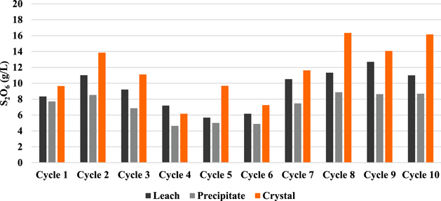
Figure 8. Dithionate concentration profile in the first locked-cycled campaign.
Download figure:
Standard image High-resolution imageTable VI shows the concentrations of sodium sulphate through the process for each cycle, calculated based on the sulphate and sodium concentrations measured in each solution. By comparing the sodium sulphate concentrations in the recycled solution with those in the leach filtrate, it can be seen that they are very close, suggesting that there is little or no formation of sulphate crystals in the leach during this locked-cycle campaign.
Table VI. Sodium sulphate concentrations (calculated) by cycle in the first locked-cycle campaign.
| Na2SO4 (g l−1) estimated based on Na in solution | ||||
|---|---|---|---|---|
| Cycle# | Recycled into leach | Leach Filtrate | Precipitation Filtrate | Crystallization Filtrate |
| 1 | — | — | 242 | 126 |
| 2 | — | 113 | 346 | 169 |
| 3 | 102 | 106 | 364 | 165 |
| 4 | 119 | 122 | 342 | 172 |
| 5 | 141 | 141 | 402 | 153 |
| 6 | 81 | 78 | 325 | 138 |
| 7 | 81 | 78 | 385 | 183 |
| 8 | 151 | 156 | 425 | 211 |
| 9 | 153 | 131 | 352 | 151 |
| 10 | 151 | 143 | 398 | 181 |
The second locked-cycled campaign repeated the leach conditions of the first (also using LCO cathode material as feed) followed by combined precipitation of Co and Li as hydroxides and carbonates. As with the first campaign, the final filtrate was treated by chilling for sodium sulphate removal prior to being recycled back to the next cycle's leach. For the second campaign, a limited re-pulp wash was added for the recovered sodium sulphate crystals and this wash solution was added to the recycled solution, along with other wash streams, which were also recycled in the first campaign. As there were higher volumes of wash water in the second campaign, to control the water balance the combined recycle stream was evaporated to the target volume before the next leach cycle, whereas in the first campaign only the dilute cobalt precipitate wash solution was evaporated to control the solution volume. Figure 9 shows the schematic of the second locked cycle campaign. The optional of nanofilter showed in Fig. 9 was not executed during the locked-cycle campaign.
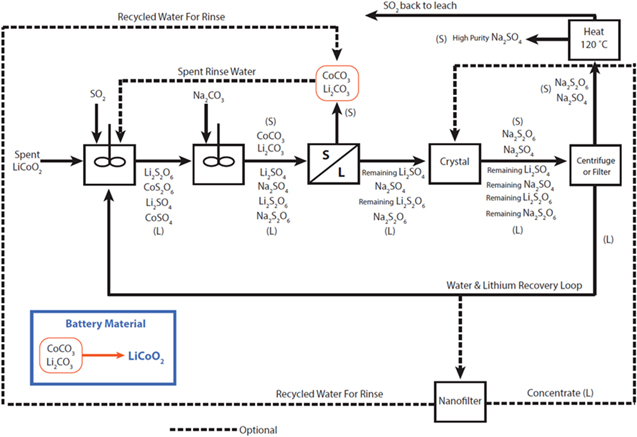
Figure 9. Second locked cycle flowsheet with simultaneous recovery of metals.
Download figure:
Standard image High-resolution imageSince the feed material and leaching conditions were similar in both campaigns, it was expected that the leaching performance would also be similar. Initially, Co extraction was near 100% and Li was above 90%, which was similar to the first campaign, but after Cycle 2 the cobalt extraction dropped significantly, as shown in Fig. 10 . The lost cobalt could be recovered from the leach residue by washing with large amounts of water, which is shown in Fig. 10 as the "Leach Wash".
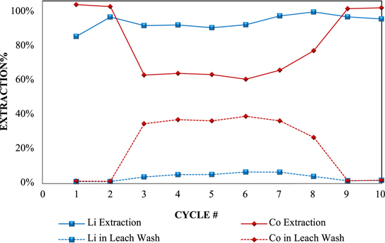
Figure 10. Second campaign-leach results.
Download figure:
Standard image High-resolution imageFollowing leaching, the solubilised metals were recovered with sodium hydroxide and carbonate as shown in Fig. 11. Overall, the recovery of lithium rises rapidly and is generally good through all cycles except the first one. Lithium recoveries were likely slightly overestimated in these tests due to the requirement for addition of a fresh saturated Li2CO3 solution to the second wash of the co-precipitated filter cake from each cycle. A theoretical saturation of lithium was used in accounting for this addition, but temperature variations likely resulted in higher concentrations. Despite this uncertainty, the overall lithium recovery appeared to be comparable to that achieved in the first campaign. Cobalt recovery was affected in early cycles by losses to crystal formation in the leach but increased in later cycles as this material was recycled back into the process. The excess recoveries for both metals in Cycle 9 reflect recovery of losses from previous cycles after decreasing the pulp density in the later cycles.
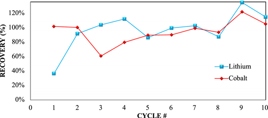
Figure 11. Metal recovery in the second campaign, utilizing single stage precipitation.
Download figure:
Standard image High-resolution imageAs in the first locked-cycle campaign, the second campaign showed consistent extraction of the metals from LCO material. The main issue was the entrapment of leached metal into sulphate crystals formed during leaching. Another indication of crystal formation was the higher mass of leached residues for Cycles #3 through #7 shown in Table VII.
Table VII. Second locked-cycle campaign—feed and products.
| Leaching Stage | Hydroxide/Carbonate Product | Sulphate Crystals | ||||||||||
|---|---|---|---|---|---|---|---|---|---|---|---|---|
| Feed | Feed | Recycle | Residue | Mass | Li | Li Rec. | Co | Co Rec. | Mass | Li | Co | |
| Li | Co | Li | ||||||||||
| Cycle ID | g | g | g | G | g | % | % | % | % | g | g Kg−1 | mg Kg−1 |
| Cycle#1 | 6.80 | 58.4 | — | 0.51 | 108 | 2.88 | 36 | 54.5 | 101 | 109 | 0.23 | 5.0 |
| Cycle#2 | 6.80 | 58.4 | 4.25 | 0.73 | 129 | 5.46 | 91 | 44.9 | 100 | 201 | 0.18 | 5.0 |
| Cycle#3 | 6.80 | 58.4 | 3.94 | 10.09 | 98 | 7.84 | 103 | 35.9 | 60 | 271 | 0.24 | 5.0 |
| Cycle#4 | 6.80 | 58.4 | 4.87 | 2.00 | 121 | 6.90 | 112 | 38.1 | 79 | 262 | 0.24 | 5.0 |
| Cycle#5 | 6.80 | 58.4 | 4.13 | 2.18 | 122 | 5.45 | 86 | 42.4 | 89 | 282 | 0.24 | 5.0 |
| Cycle#6 | 6.80 | 58.4 | 4.25 | 3.85 | 122 | 5.93 | 99 | 42.5 | 90 | 211 | 0.67 | 6.0 |
| Cycle#7 | 6.80 | 58.4 | 4.43 | 3.42 | 143 | 5.17 | 102 | 39.9 | 99 | 221 | 0.35 | 5.0 |
| Cycle#8 | 6.80 | 58.4 | 3.67 | 0.69 | 161 | 4.01 | 87 | 33.6 | 93 | 255 | 0.34 | 8.2 |
| Cycle#9 | 6.80 | 58.4 | 3.98 | 1.27 | 168 | 5.99 | 134 | 41.8 | 121 | 393 | 1.59 | 5.0 |
| Cycle#10 | 6.80 | 58.4 | 5.15 | 1.48 | 147 | 5.79 | 114 | 41.3 | 105 | 314 | 0.34 | 5.0 |
Figures 12 and 13 show sulphate and dithionate levels in the leach, in precipitation filtrates and after sulphate crystal removal. The sulphate concentrations in leach filtrates are consistently higher (>300 g l−1 SO4) when compared to the first campaign (Fig. 7). In addition, it is noteworthy that high levels of dithionate in Cycles 3 and 4 coincide with the lowest extractions of Co in the leach stage.

Figure 12. Sulphate concentration profile in the second locked-cycled campaign.
Download figure:
Standard image High-resolution image
Figure 13. Dithionate concentration profile in the second locked-cycled campaign.
Download figure:
Standard image High-resolution imageTable VIII presents the calculated sodium sulphate levels in the principal process streams for each cycle. The sodium sulphate in the recycled solution is over 220 g l−1 while the leach filtrate is significantly lower, with concentrations between 145 and 164 g l−1. This confirms the formation of sodium sulphate crystals during leaching. The high sulphate concentrations in the recycle stream are due to the evaporation of the combined process solutions to control the water balance.
Table VIII. Sodium sulphate concentration (calculated) per cycle in the second locked-cycle campaign.
| Na2SO4 (g l−1) estimated based on Na in solution | ||||
|---|---|---|---|---|
| Cycle# | Recycled into leach | Leach Filtrate | Precipitation Filtrate | Crystallization Filtrate |
| 1 | — | 0.1 | 188 | 102 |
| 2 | 161 | 163 | 342 | 203 |
| 3 | 228 | — | 362 | 95 |
| 4 | 227 | 164 | 276 | 94 |
| 5 | 226 | 145 | 375 | 89 |
| 6 | 229 | 149 | 354 | 78 |
| 7 | 224 | 161 | 385 | 91 |
| 8 | 214 | 179 | 357 | 71 |
| 9 | 183 | — | 331 | 101 |
| 10 | 203 | 195 | 422 | 86 |
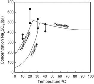
As simple as sodium sulphate chemistry might seem, its crystallization behaviour can be a complex phenomenon. As many as three phases may form under certain condition: stable thenardite, (Na2SO4) and mirabilite, (Na2SO4 × 10H2O) as well as a metastable heptahydrate, Na2SO4 × 7H2O. In a system involving more than a single solid phase, metastable Na2SO4 × 7H2O may be expected to crystallise and it is not always reproducible. 13 The residence time is also an important factor in the formation of precipitates. Considerable care must therefore be taken to ensure solution concentrations are well below the saturation levels. High levels of hydration with sodium sulphate crystals can also increase crystallization by removing water from the system. Figure 14 shows the solubility curves for all three phases of sodium sulphate and it shows that sodium sulphate levels over 200 g l−1, as observed in the second locked-cycle campaign, could have generated crystals in the leach solution.
Figure 14. Solubility curves for Thenardite, mirabilite and heptahydrate phases. 13
Download figure:
Standard image High-resolution image
The experimental evidence collected in both campaigns showed that both simultaneous and sequential precipitation methods were successful, recovering over 90% of cobalt and lithium from LCO active cathode material, although the grades of cobalt and lithium in the products were higher (60% for Co and 18% for Li, Table V) using sequential precipitation with hydroxide for Co and carbonate for Li compared with the single combined product (about 40% Co and 6% Li average for 10 cycles, Table VII). The control of sulphate levels in the recycle stream with crystallization should be an important addition to the earlier bench optimization study and it could prove to be a necessary step to prevent losses associated with sulphate crystal formation due to circulating sulphate loads in recycle streams. In addition to sulphate, the dithionate generated in the leach can increase with recycle but does not reach saturation levels. When dithionate concentration reaches saturation, it could also be controlled by crystallization along with sulphate. 14
The principal difference between the first locked-cycle campaign and the second locked-cycle campaign as shown in Figs. 4 and 9 lies in the metal precipitation stage. The flowsheet in Fig. 4 recovers cobalt separately from lithium, while the flowsheet in Fig. 9 uses a single stage to produce a combined Co/Li product. Both flowsheets include the crystallization stage and recycled streams (remaining lithium and sodium) to minimize water consumption and maximize lithium recovery in the system. On a larger scale, dilute wash recycle streams can be treated by nanofiltration to produce clean water for washing products and to control the overall water balance rather than using evaporation. The concentration from nanofiltration may be recycled back to the crystallizer to maximize sodium sulphate removal.
Conclusions
The current study evaluates the sulphuric acid/sulphur dioxide leach system to recover metals from NMC, NCA, LMO, and LCO lithium cathode materials. Excellent (>99%) extractions for all metals (Li, Co, Ni and Mn) are achieved within 2 h at 10% solids, 0.8−1 M H2SO4, pH 1 to 1.5 and with sulphur dioxide targeting ORP in the range of 350–630 mV. Along with the extracted metals, the method can generate high concentrations of sulphate and dithionate in leach solutions that are needed to be controlled in circulating loads, which are required for high lithium recovery.
Cobalt and nickel can be effectively precipitated from leach solutions by modifying the pH to 10 with NaOH, or with sodium sulphide after neutralizing to pH 5 with NaOH. At pH 10, a complete recovery of leached manganese is also achieved, with the most effective separation of manganese from cobalt and nickel obtained with sulphide precipitation. The optimal pH for selectively precipitating aluminium from leach solutions was 5.5. The lithium recovery is incomplete in batch experiments, but with process solution recycling in the locked-cycled campaigns, it is shown that lithium recovery can be greatly improved, from 30% or less in batch tests to levels exceeding 90% after establishing the circulating load. The cobalt recovery from LCO cathode material in two locked-cycle semi-continuous campaigns is consistent and essentially completed in each cycle. However, when sodium sulphate concentrations in the recycle stream exceeded 200 g l−1, a portion of the leached cobalt is entrained by sodium sulphate crystallization during the leach. Sodium sulphate crystallization is the result of sulphate ions from the leach acid combining with the sodium ions from neutralizing the acid. Although different cathode materials might end up consuming different amounts of acid, sodium sulphate crystallization will be problematic for all cathode materials as sulphate ion and sodium ion concentrations are built up during the locked-cycle close-loop process. The sodium sulphate crystals have to be solubilised with additional water in order to recover the entrapped cobalt. Therefore, one of the significant conclusions from these campaigns is the importance of optimizing the sodium sulphate crystallization stage prior to recycling the process solutions back to the leach stage when sulphuric acid and sodium-based reagents are being utilized in the recycling of cathode materials. On the other hand, the two locked cycle campaigns demonstrate an environmental friendlier closed-loop hydrometallurgical process that reduces discharges and minimizes environmental impact for recycling lithium ion battery cathode materials.
It will be also important to test the developed locked-cycle processes on other cathode materials like NMC, NCA, and LMO as well as test the locked-cycle processes in pilot scale to further explore the operation economy.
Acknowledgments
This work was supported by the Shanghai University PhD Programs and the Project of Establishing Shanghai University Institute for Sustainable Energy Co-Funded by Shanghai Education Administration Committee and Shanghai University.